Vessels which are lying at a river berth or in tidal conditions when strong currents are running. Under these conditions the draught marks should ideally be read over periods of slack water (provided that at a low water slack there is sufficient under-keel clearance). Currents of appreciable strengths are likely to cause the vessel to change trim or pitch slightly and/or sink bodily into the water from her static draught (squat).
This phenomenon becomes more pronounced in shallow waters (shallow water effect). - Strong currents will result in raised water levels against the leading edge of a stationary vessel lying in flowing water. This is especially true when the flow is in the direction of a vessels bulbous bow.
Draught marks must be read on both sides of the vessel: forward port and starboard; amidships port and starboard, and; aft port and starboard or, alternatively, if additional marks are displayed on large vessels at all the designated positions.
Should draught marks not be in place amidships, distances from the deck line to the water line on both sides of the vessel must be measured. The amidships draughts can then be calculated from load line and freeboard data extracted from the vessels stability booklet.
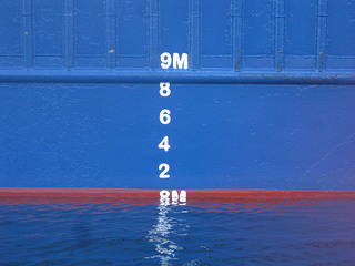
Draught marks should be read with the observer as close to the water line as is safe and reasonably possible, in order to reduce parallax error.
Although it is common practice to read the offside draught marks from a rope ladder, a launch or small boat provides a more stable environment and brings the observer to a safer position closer to the water line.
A vessels remote draught gauge should never be used for surveys, due to lack of the necessary accuracy and the possibility of errors, which may accumulate over the working life of the instrument.
When adverse weather conditions are being experienced, access to the offside draught marks may prove difficult or impossible. At these times the draughts on the nearside can be read and the offside draughts calculated using a manometer .
This method should never be used when the offside draughts can be safely observed and accurately read. If, as a final resort, this method cannot be undertaken, the use of a fully calibrated inclinometer, graduated to minutes of arc, is strongly recommended. The type of inclinometer fitted to vessels is not usually of sufficient accuracy to be used.
Density of the water in which the vessel is floating
It is prudent to obtain samples of water in which the vessel is floating at, or very close to, the time at which the draught marks are read. This is particularly relevant when the vessel is lying at a estuarial or river berth when density of the water may be changing, due to the ebb or flow of the tide.
Depending upon the length of the vessel under survey, a number of samples, say between one and three, should be taken. In order to overcome the problem of layering, the samples should be obtained using a closed sampling can at a depth of approximately half the existing draught of the vessel.
Alternatively, a slowfilling container can be used to obtain an average sample from keel to waterline. When reading the hydrometer floating in the sample of water, the eye of the observer should be as close to the water level as possible, to avoid parallax errors and also to avoid further errors due to the meniscus .
Ballast water tanks
Ballast water tanks including peaks, even those said to be empty, must be carefully sounded or proven to be full by pressing up and overflowing from all air pipes when local regulations permit. If the ballast hold contains ballast water, this compartment must not be fully pressed up but be carefully sounded and the weights of the water carefully calculated.
Spaces such as the duct keel and voids especially those of the lower stools situated at the base of transverse bulkheads, between cargo holds must be checked when safe to do so, and proved in same condition at initial and final surveys.
These voids often contain the manhole access covers to the adjacent double-bottom tanks. If these covers are not totally watertight, then the voids will flood, or partially flood, during ballasting or pressing up of the tanks, potentially resulting in huge errors in the lightship or ballast survey.
As noted above, the calculation of the weight of ballast water is undoubtedly the most usual source of errors which may result in very large, and unacceptable, inaccuracies of the cargo quantity as calculated by draught survey.
Density of the ballast water
It should be established, with the chief officer, where the various ballast tanks were filled. If from a single source, the sea, a few random samples of the water will confirm its density. If from different sources, docks or rivers, etc samples must be taken from the tanks containing water from these various sources and relevant densities of the water in individual tanks established.
Do not overflow the tanks substantially to obtain samples unless local regulations permit; instead use sampling equipment suitable for tanks that are only partially filled.
When small samples are obtained, use a salinity refractometer to establish density (see below). When larger samples have been obtained, a draught survey hydrometer may be used. See details above.
Establishing the correct weights of oils on board
This can be established either by sounding or ullaging of the tanks or, in the case of the engine room daily service and settling tanks, by reading the gauges.
The volumes of oils in each and every tank should be measured and recorded.
The relative densities of the most recently delivered oils on board can be obtained from the bunker delivery certificates. However bunkers are almost inevitably mixed with oils already on board, the densities of which are likely to differ.
The relative density of the contents may be calculated using the following formula: RD of tank contents at survey = (Old oil volume x Old RD) + (New bunker volume x New RD) Total volume of oil in tank
After completion of the bunker survey the totals of each oil found must be agreed with the chief engineer and the master.
Calculations & associated corrections of vessels displacement from draught readings
Before extracting hydrostatic data from the vessels stability book, care should be taken by surveyors to familiarise themselves with the format and methods used to display the various particulars, especially the means of depicting positions of Lcf (longtitudinal centre of flotation) etc, relative to amidships or alternatively the after perpendicular.
When using a recommended draught survey computer programme or alternatively calculating directly from data extracted from the hydrostatic particulars contained within the vessels stability book it is essential that the data is carefully and properly interpolated or, in what should prove to be a rare event, extrapolated.
As mentioned below, one of the areas where significant errors often result is from the incorrect application of the sign in respect of the position of the Lcf (in the first trim correction).
When undertaking initial and final displacement draught surveys to establish weight(s) of cargo loaded, or alternatively unloaded, the difference between the net displacement weights provides the total cargo quantity.
Nonetheless it is recommended for a cross check that, at the light ship/ballast survey, the vessels light ship weight is deducted from net displacement found. The resultant then provides the vessels constant at that time. These unknown weights might also be termed the vessels stores variable. Although variable, for a number of reasons as later discussed, it should serve as a guide to the accuracy of the light ship/ballast survey.
Comparison between stores variable quantities, or mean thereof, established at previous surveys should be treated with caution unless the variable is a direct comparison that can be made. For example, all surveys include a check and a record of the engine lubricating oil held in storage tank(s), etc.
Occasionally, surveyors report a negative stores variable which is theoretically impossible unless, in extremely rare instances, the vessel had been subject to modification, and large quantities of structural steel removed, without being subject to a further inclining experiment and commensurate correction of the relevant data contained in the vessels stability book.
Charterparties often contain reference to an approximate quantity for the vessels constant, which may well create a discussion between master and surveyor should the constant found by survey to be substantially larger than that quoted by the owners.
The surveyor, after relevant checks, should remain confident in the figure obtained, but always record on documents issued to the master and clients, any unusual factors or difficulties experienced during survey. These include any differences between surveyors, should owners, charterers or shippers each appoint separate survey companies to act on their behalf.
Documentation
At completion of survey, a survey work sheet or computer printout should be placed on board the vessel recording the data and calculations used to obtain the cargo loaded/ unloaded quantity. This document is usually produced by individual survey companies, or by shipping companies for use by their officers.
A formal survey report should be submitted to clients at a later date. Specific formal documentation has been drawn up, amongst others by IMO, United Nations Economic Commission for Europe and various P&I Clubs.
The formal report document should not only include details of the survey, but also:
- Dates and times of surveys. Vessel particulars.
- Ships location.
- Weather conditions (and whether these were within acceptable limits).
- Sea conditions (and whether these were within acceptable limits).
- Tidal/current conditions (and whether these were within acceptable limits).
A record of any difficulties or defects in a ships documentation or equipment which might cause the calculated weight by draught displacement survey to be outside acceptable limits of normal draught survey measurement error.
Expert opinion
Surveys must be carried out to the very best of the surveyors ability, with each part of the survey conducted as accurately as possible in order to minimize procedural and/or measurement errors which could effect the quantity of cargo recorded by survey as being loaded or discharged.
The final report should include details of any defect or circumstance regarding weather, surface water, tides/ currents or on board conditions which the surveyor considers might well influence the result adversely.
Cumulative errors
- Errors can occur when reading and correcting the draughts. The final fully corrected 3/4 mean draught should be within +/- 10 mm of the true mean draught.
- Errors of calculation. The main error to be avoided in this section is that of incorrectly positioning the LCF relative to LBP/2 the amidship point.
- Error of the water density in which the vessel is floating. Always ensure an average sample, or alternatively the average of a number of water samples are obtained and the correct type of certificated hydrometer is used to obtain the density.
- Sounding of tanks. Leaving aside documented tables which may not be accurate, the way of avoiding the main errors in this section of the survey is by ensuring, as best possible, that all volumes of liquids, especially ballast water, on board are both correctly quantified and attributed with correct densities. These factors, particularly when applied to ballast water, undoubtedly contribute to the largest number and degree of errors likely to be encountered in draught surveying.
Bearing these reservations in mind, a well conducted draught survey under reasonable prevailing conditions is capable of achieving an absolute accuracy of +/- 0.5%
Important terms related with ships draft survey and cargo calculation
Displacement
The quantity of water displaced by the underwater volume of the hull. When expressed in tonnes it equals the weight of the ship at any given draught.
Light Displacement
The quantity of water displaced by the vessel in its light condition, which includes the ship, all equipment, spare parts for machinery, water in boiler to working level and lube oil for engines. It is also referred to as `lightship', which is established by an inclining experiment when the ship is built. However, lightship is likely to change with the age of the ship due to additional equipment and spare parts, additional layers of paint, mud/sludge in ballast/fuel tanks and other weights. It is estimated that an extra 0.2% of weight is added to a vessel every year.
Lightship Constant
This is the difference between the lightship found in a draught survey and that given in the stability booklet. When found, it should be recorded for reference in future surveys.
Arithmetical Mean Draught (AMD)
This is the mean of forward and aft observed draughts. If the vessel is neither hogged nor sagged, then AMD should be equal to the midships' draught.
True Mean Draught (TMD)
The draught of the vessel at the LCF. This draught is used to find the values from the hydrostatic particulars of the vessel given in the stability information booklet
Forward Perpendicular (FP)
A perpendicular drawn to the water line at a point that intersects the summer load line and the stem of the vessel.
Aft Perpendicular (AP)
A perpendicular drawn to the water line at a point that intersects the summer load line and the stern post of the vessel.
Length between Perpendiculars (LBP)
Length of vessel between FP and AP.
Tonnes per Centimetre (TPC)
The weight that must be loaded or discharged to change a ship's mean draught by one centimetre. Moment to Change Trim by One Centimetre (MCTC) The moment required to change the trim of the vessel by one centimetre.
Longitudinal Centre of Flotation (LCF)
Distance of the centre of flotation of the vessel from AP (or from midships). It is the point about which the vessel trims and is the centroid of the waterplane area of the vessel.
Layer Correction
Also known as 1st Trim Correction, it is the difference between the TMD and AMD.
Liquid Quantities in Tanks
These are important for correct estimation of cargo quantities loaded, and are established by obtaining soundings/ullages of the tanks and then finding the volume from sounding tables. The volume obtained should then be converted to weight based on the density obtained from samples of the liquids and/ or that given for fuel oils by the chief engineer. Trim and list corrections should always be applied to the soundings/ullages obtained for all tanks.
Top articles
- Indication of unusual motion or attitude of bulk carriers and risk management / evacuation
- Deterioration of ships structure and consequences of forward flooding
- Handling water ingress problems in bulk carrier, investigation and countermeasures
- Survival and safety procedure for bulk carriers
Our detail pages illustrated many safety aspects of Bulk carrier
Home page |||Bulk carrier types ||| Handling of bulk coal |||Cargo planning ||| Carriage of grain |||Risk of iron ores |||Self unloading bulk carriers |||Care of cargo & vessel |||Cargoes that may liquefy |||Suitability of ships |||Terminal guideline |||Hold cleaning |||Cargo cranes |||Ballast handling procedure |||Bulk carrier safety |||Fire fighting systems |||Bulk carrier General arrangement
Top articles
- Cargo damage survey guideline
- Cargo handling guideline for bulk carrier
- Classification of various dry bulk commodities

Operation of sea going bulk carriers involved numerous hazards . Careful planning and exercising due caution for all critical shipboard matters are important . This site is a quick reference to international shipping community with guidance and information on the loading and discharging of modern bulk carriers so as to remain within the limitations as specified by the classification society.
It is vital to reduce the likelihood of over-stressing the ship's structure and also complying with all essential safety measures for a safe passage at sea. Our detail pages contain various bulk carrier related topics that might be useful for people working on board and those who working ashore in the terminal. For any remarks please Contact us
Copyright © 2010 bulkcarrierguide.com All rights reserved.
Although every effort have been taken to improve the accuracy of content provided the publisher of this website cannot gaurantee for errors. Disclaimer Privacy policy Home page