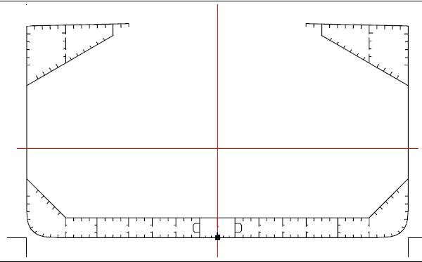
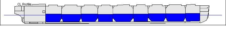
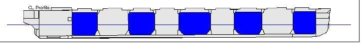
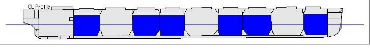
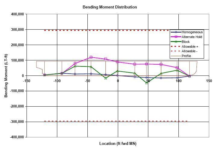
Figures above compare the shear and bending moment distributions for the various loading patterns. All three patterns carry the same total amount of cargo.
In addition to the final loading condition of the vessel, careful planning must go into the sequence in which holds and tanks are loaded and unloaded. Shear and bending moment are to be minimized throughout the loading and unloading process. The ships crew must work closely with the terminal personnel to plan and monitor the rate of loading, the weight of cargo to be loaded and how it is to be measured, any vessel shifts that will be necessary, draft checks to confirm the weight of cargo loaded and to ensure that intermediate loading still satisfies the limitations based on local draft.
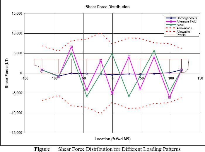
Fig:Shear Force Distribution for Different Loading Patterns
In June 2000, the ALGOWOOD buckled while loading sand and aggregates at Bruce Mines, Ontario, Canada. While a loading sequence had been predetermined, it was modified in the field when the vessel was unable to shift as far aft in the berth as called for. Investigation by Transport Canada found that the bending moment at the time of the failure was 2.3 times the allowable still water bending moment.
During the loading and unloading process heavy equipment is used that can cause heavy wear on the cargo hold structure. Cargo is loaded using conveyor belts and may be dropped from the main deck height to the bottom of the hold. Unloading, clamshell grabs may be used when the ship is not a self-unloader. These grabs can weigh as much as 30tons without their cargo and are dropped and scraped against the tank top. Hydraulic hammers may also be used to dislodge cargo from corners and around framing. All of these practices can lead to rapid degradation of coatings and steel.
Steel Corrosion
Steel corrosion is a chronic problem aboard bulk carriers. They are perhaps more susceptible than other large vessels such as tankers and container ships due to the nature of their construction and operation. Protective coatings are compromised by the use of heavy equipment for loading and discharge.
Some cargoes themselves can create a more corrosive environment than water. And the use of high strength steel makes the vessel structure particularly vulnerable to strength degradation due to corrosion. In September of 2000, EUROBULKER X broke apart while loading cement at Lefkandi Greece. A fifteen month inquiry pointed to a variety of mitigating factors, one of the largest being severe corrosion. Lower deck plating was wasted 30-40 percent and upper ballast tanks ranged from 50 percent to completely wasted in some areas. In addition the loading sequence allowed cargo to be loaded amidships with the fore and aft holds empty.
Coatings :
Cargo holds of bulk carriers are typically coated with a complex system of several coats of epoxy. While there are international standards for coatings in ballast tanks and voids, coatings for bulk carriers are highly dependent on the cargo to be carried. The abrasiveness of the cargo itself and the use of grabs, hammers, and other heavy equipment can rapidly compromise coatings. Once the coating is penetrated, the steel itself is subject to corrosion.
Cargoes :
A wide variety of cargoes are carried in bulkers, ranging from grain to coal to iron ore. The physical and chemical properties of the cargo carried can have a substantial impact on the rate of corrosion of a vessels structure. Sulphur residue in coal cargoes can combine with water to form sulphuric acid. Some cargoes have a residual moisture content that contributes to the humidity in the hold. Some cargoes can cause internal heating within the hold.
High Strength Steel :
Many bulk carriers of the 1980s were designed with high tensile steel to improve their structural strength. Although this is an effective way to add to the strength of the new vessel, it can be problematic once corrosion sets in. While high tensile steel can be thinner than mild steel for the same strength, it will corrode at the same rate.
Related articles
- Structural integrity & design limitations of modern seagoing bulk carriers
- Design of ships longitudinal subdivisions & of transverse watertight bulkheads
- Bulk carrier
General arrangement
- Bulk carrier corrosion rates and preventive measures
- Definitions of available Bulk carrier sizes
- Tank construction & required strength for ships carrying bulk cargo
- Handling water ingress problems in bulk carrier, investigation and countermeasures
- Survival and safety procedure for bulk carriers
- Hatch cover strength requirement for a seagoing bulk carrier
Top articles
- Indication of unusual motion or attitude of bulk carriers and risk management / evacuation
- Deterioration of ships structure and consequences of forward flooding
- Handling water ingress problems in bulk carrier, investigation and countermeasures
- Survival and safety procedure for bulk carriers
- Suitability of Shore Terminals for handling bulk cargo
- Preparation for ships carrying bulk cargo & standard loading condition
Our detail pages illustrated many safety aspects of Bulk carrier
Home page |||Bulk carrier types ||| Handling of bulk coal |||Cargo planning ||| Carriage of grain |||Risk of iron ores |||Self unloading bulk carriers |||Care of cargo & vessel |||Cargoes that may liquefy |||Suitability of ships |||Terminal guideline |||Hold cleaning |||Cargo cranes |||Ballast handling procedure |||Bulk carrier safety |||Fire fighting systems |||Bulk carrier General arrangement
 Operation of sea going bulk carriers involved numerous hazards . Careful planning and exercising due caution for all critical shipboard matters are important . This site is a quick reference to international shipping community with guidance and information on the loading and discharging of modern bulk carriers so as to remain within the limitations as specified by the classification society.
It is vital to reduce the likelihood of over-stressing the ship's structure and also complying with all essential safety measures for a safe passage at sea. Our detail pages contain various bulk carrier related topics that might be useful for people working on board and those who working ashore in the terminal. For any remarks please Contact us
Copyright © 2010 bulkcarrierguide.com All rights reserved.
Although every effort have been taken to improve the accuracy of content provided the publisher of this website cannot gaurantee for errors. Disclaimer Privacy policy Home page