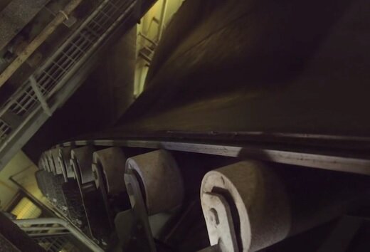
Fig:self unloader components maintenace
The following items are to be entered in the vessels planned maintenance system with the relevant parameters and periodic maintenance required:
- Pulleys
- Drive Motors
- Fluid Drives
- Couplings
- Tanks and draft gauges
- Accumulators
- Tensioning Units
- Boom Hoist
- O speed circuits
- Low Level pressure circuits
- High temperature circuits
- Loop belt safety beam
- Bulldog grips
- Scrappers
- Ploughs
- Impact plates
- Hydraulic components
- Hydraulic oil filters
- Hydraulic oil analysis
- Air Filters
- Hydraulic oil reservoir
- Hydraulic pipework
- Hydraulic valves
- Hydraulic pumps
- Greasing/Lubrication (or as per planned maintenance system)
The greasing and lubrication schedules are to be in accordance with the manufacturers recommendations.
The lubrication of tunnel rollers, gate wheels and spindles etc which are subject to hosing down, and also bearings exposed to weather, is to be carefully monitored, and the frequency increased as necessary.
- Maintenance Of Fluid Drives (or as per planned maintenance system)
- Check and maintain oil level in the reservoir.
- Lubricate flexible couplings in accordance with the manufacturers instructions.
- Lubricate all bearings during operation.
- Check condition of oil and renew as recommended.
- Maintenance Of Reduction Gears (or as per planned maintenance system)
- Oil must be checked for degradation which could be caused by the varying, and often high temperatures. The oil renewal time and grade of oil will be specified by the manufacturer.
- Oil seals are to be renewed whenever they show signs of leakage, or when opened for overhaul.
- The shaft bearings are to be greased in accordance with the manufacturers instruction.
- Care must be taken not to over grease the reduction gear bearings, as this may cause the grease to enter the oil bath inside.
- The pressure release nozzle provided at the top must not be allowed to become blocked.
- Start the reducer under no load first to allow the oil to reach its normal operating viscosity in low ambient temperatures. This will ensure proper lubrication and prevent seizing.
- Maintenance Of Couplings (or as per planned maintenance system) Internal inspection, greasing, and adjustments, are to be in accordance with the manufacturers instructions. Greasing is normally carried out using an LTG grease, however if another grade of grease has been used, the frequency of the internal inspections must be increased.
- Gear Couplings (or as per planned maintenance system)
Inspection, maintenance and greasing using LTG or EP grease is to be used in accordance with the manufacturers instructions.
For gear couplings: an LTG or EP grease is recommended. Grease the couplings periodically according to set recommended intervals. These may require more frequent greasing if operating under higher loads. Frequent axial movement, high temperatures or moisture. This gear coupling must be opened periodically to inspect all internal parts and check for the wear gear teeth and hub face. Renew seal rings, bolts and gaskets, and pack the hub teeth with grease when assembling. All settings of the assembly are to be done as per manufacturers instructions.
- Maintenance Of Gantry Crane (or as per planned maintenance system)
- Diesel engine lubrication.
- Lifting hydraulics.
- Foot brakes.
- Limit switches.
- Rail to be kept clear.
- Limits of trim of the vessel for operation.
- Inspect track weld onto the deck.
- Hoist and lower pontoons steadily.
- Electrical cable to be clear of track and obstructions.
- Charging battery.
- Defect Reporting
Belt mechanical fasteners
Mechanical fasteners are used in emergency situations to repair a tear or rip in all types of belt except the steel cord type. They are manufactured from corrosion resistant metals, and are in the form of clamps, hinged pins and bolted plates.
Long term repairs can also be effected using these fasteners, however the type of fastener and the belt preparations are important. The use of fasteners however reduces the belt strength, adversely affects the cleaning, results in wear of the pulley lagging, and allows leakage of cargo material on to the return belt, and its mechanical components.
It is essential that mechanical fasteners are inspected at regular intervals and renewed as required. The special tools and manufacturers instructions for the mechanical fasteners must be kept on board at all times.
The following is a typical list of fasteners and special tools to be carried on each vessel:
200 each, #190 Flexco Fasteners
each, 2¼ Flexco Fasteners)
2 each, HP1 Punches for Flexcos
2 each, HW1 Wrenches for Flexcos
1 each, 110 Bolt Breaker
12 each, units of QBM 327 Repair Putty
60 each, QBM 327 Dispenser Nozzles
6 each, Cartridges E6100 Adhesive
4 each, quarts Pangofol Adhesive/Harder
10 gallons, Toloul Solvent
TOOLS
1 each, Half Inch Drive Impact Gun
1 each, Slow Speed Buffer and Wire Cup
1 each, QBM 327 Cold Cure Dispenser Gun
1 each, Quick Change Chuck for Impact Gun
Belt rubber repair kit
The rubber repair kit consists of a non-flammable polyurethane resinous compound and an accelerator. When these parts are mixed together in the proportions specified in accordance with the suppliers instructions, they form a tough flexible rubber-like compound. The two parts when mixed have a potlife of not more than ten minutes. This method of repair is for minor superficial repairs, e.g. filling rips and gouges on the surface of the belt, rubber linings etc. The rubber-like compound requires 12 to 24 hours for curing, but after two hours of application the belt can be used if necessary. The Rubber Repair Kit must be available on board at all times.
Another method to repair rips and gouges on the belt is by the use of Rubber Patches, and these are of various types:
- moulded rubber patch for rips and gouges, also to seal frayed belt edges
- fabric re-inforced patch, used on the bottom cover for impact breaks
- large rubber sheeting used with a chemical bonding layer for a quick repair of the top cover.
A saddle is a piece of belt of similar specification and required length, which is inserted in the damaged section of the belt by using mechanical fasteners, or by vulcanised splicing. Usable or good sections of a belt being discarded are to be retained onboard for possible use as saddle or short belts.
Where major repairs are required on short belts such as a transfer belt, it is the preferred option to renew the belt in its entirety.
Note: each vessel is issued with a checklist for belt repair materials and tools. It is the responsibility of the chief engineer to ensure that these tools and materials are maintained at the correct stock levels and that repair compounds and rubber are stored in a suitable environment to prevent decay.
Belt hot vulcanised splice
Hot Vulcanised Splices utilise heat and pressure to form a permanent repair and are used in the splicing of newly installed belts to form a loop. The splice is formed by stripping back the belt layers to form steps, and impregnating the layers with glue, placing the ends together and covering them with rubber. The splice area is then held under pressure by specially constructed transverse bars of a cooker, which has heating elements.
When using the cooker, it is essential that the correct voltage and phase are supplied, it is well grounded, and the area of usage is clean and free from dampness. All insulation must be tested. Hot vulcanising can be carried out on any belt type, and is to be considered as a permanent repair. It is used in splicing both damaged and newly installed belts. Hot splicing carried out correctly does not appreciably reduce the belt strength. It is the best and only method to splice steel chord belts. The belt performance will be adversely affected if the splice is unsatisfactory and results in the non-linearity of the belt, and will cause mis-training.
Belt vulcanising equipment
The vulcanising equipment, and support tools must be well maintained, and stored in a cool, dry, dust free space. An inventory of its components must be carried out regularly.
UHMW Sheets Hold lining
The UHMW lining in the cargo holds must be checked following each discharge. Removal of this sheeting with its securing studs must be carried out at the first opportunity. It is essential that the manufacturers instructions for the use of the stud welding guns are complied with and in particular the following points:
- Correct surface preparation
- Recommend current settings
- Regular re-calibration of the guns
- No stud welding on surfaces common or adjacent to fuel oil tanks.
Related information
Self unloader components
Function of loop & bucket belt elevators
Self unloaders various cargo handling gears
Various type boom conveyor belts - How the belt sytem practically works ?
Dealing with self unloaders stalled lift belt
Conveyor belt construction & troubleshoot guide
Conveyor belt installation guide
Our detail pages illustrated many safety aspects of Bulk carrier
Home page |||Bulk carrier types ||| Handling of bulk coal |||Cargo planning ||| Carriage of grain |||Risk of iron ores |||Self unloading bulk carriers |||Care of cargo & vessel |||Cargoes that may liquefy |||Suitability of ships |||Terminal guideline |||Hold cleaning |||Cargo cranes |||Ballast handling procedure |||Bulk carrier safety |||Fire fighting systems |||Bulk carrier General arrangement
 Operation of sea going bulk carriers involved numerous hazards . Careful planning and exercising due caution for all critical shipboard matters are important . This site is a quick reference to international shipping community with guidance and information on the loading and discharging of modern bulk carriers so as to remain within the limitations as specified by the classification society.
It is vital to reduce the likelihood of over-stressing the ship's structure and also complying with all essential safety measures for a safe passage at sea. Our detail pages contain various bulk carrier related topics that might be useful for people working on board and those who working ashore in the terminal. For any remarks please Contact us
Copyright © 2010 bulkcarrierguide.com All rights reserved.
Although every effort have been taken to improve the accuracy of content provided the publisher of this website cannot take responsibility for errors. Disclaimer Privacy policy Home page